WorkFlow designer
The tab allows you to create and visualize workflows in an easy and convenient manner. The WorkFlow designer window is composed of three basic sections, i.e. the diagram area, components bar, and options bar.
Creating a workflow consists of the following operations:
- creating steps,
- adding paths to link steps,
- adding actions on a step or path.
To design a workflow, you can use a dedicated Designer tab displayed in the upper part of the Designer Studio general window. Please note here that it appears only after opening the WorkFlow designer tab in the workflow window.
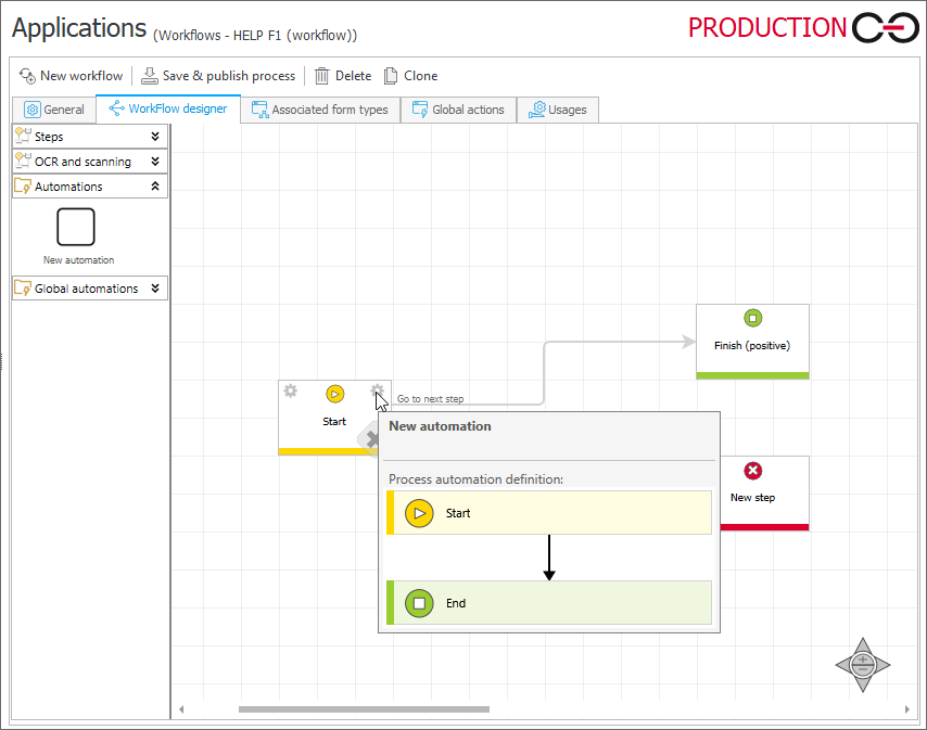
WorkFlow designer window
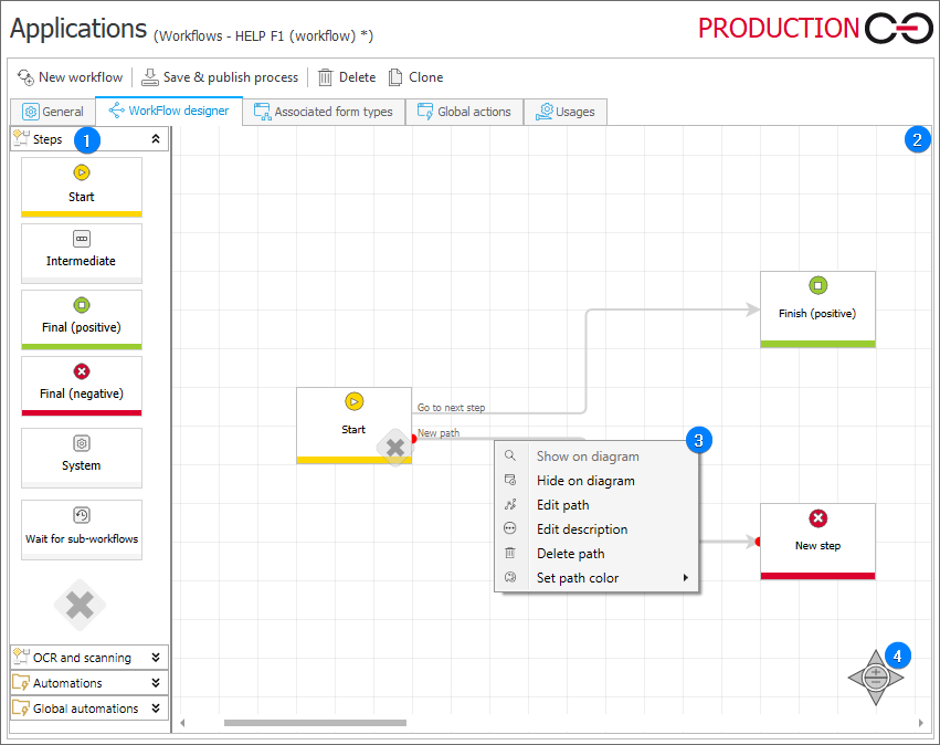
1. Steps
The panel on the left includes steps and automations which you can place on the diagram using the drag-and-drop method.
Please note that you can drop automations on path, on entry to a step or exit from it. Additional methods of invoking actions and automations are discussed in the Actions chapter.
You can use the Description field available in the step edition window to describe step function. This description is then displayed as a tooltip after hovering mouse pointer over the step icon in the diagram.
2. Working area
An area where a concrete document workflow is created. It is possible to add a note in the diagram area, but the note and its content are visible only on the diagram.
3. Path context menu
To display path context menu, right-click the path. The menu allows you to execute various operations related to the specific path, i.a. color the path with one of the eight available colors (the Set path color option).
4. Navigation control
It is used to move inside the diagram area and zoom in or out. Additionally, it is possible to move the diagram with keyboard directional keys and zoom it in or out by holding the Ctrl key and scrolling.
Workflow components
Steps
A workflow step is a point where the workflow stops to enable execution of a task assigned to specified individuals. Such step is represented on the diagram in Designer Studio by a tile whose exact appearance depends on the type of a given step. You can add step tiles to the diagram with the drag-and-drop method. There are several step types available: Start, Intermediate, Final (positive), Final (negative), Wait for sub-workflows, System, and Workflow control.
Every workflow must include a Start step and at least one final step (positive or negative one). By default, Start and Final (positive) steps (linked with a path) are embedded when a new process is created.
By single-clicking a step tile, you select it, which is indicated by adding a frame to it. To open the step edition window, double-click the tile or right-click it and select the Edit step option from the context menu. Additionally, clicking the step name area allows you to change its name.
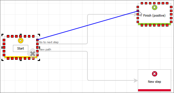
Paths
Those elements logically connect steps and enable navigation between them (provided there is a bigger number of paths branching out from the step). On the diagram, paths are presented as lines connecting individual steps or returning to the same step. Each step can hold any number of outgoing and incoming paths. You can create paths on the diagram by clicking one of the red boxes that appear after selecting a step, and dragging and dropping it on the target step.
By right-clicking the path, you expand the context menu that includes a number of options.
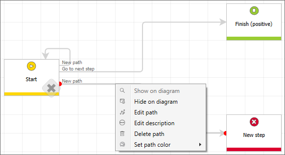
The options provided in the context menu include:
- Show on diagram – the path is visible both on the diagram and the workflow,
- Hide on diagram – the path is invisible both on the diagram and the workflow,
- Edit path – opens path edition window,
- Edit description – allows to enter path description displayed after hovering over the path presented on the diagram,
- Delete path – deletes the selected path from the workflow, including automations embedded on it,
- Set path color – the node allows you to choose the path color. The path coloring function is especially useful in the case of complex workflows where it helps user to distinguish individual paths.
To learn more about configuring default values, read the ARTICLE available on the WEBCON Community website.
Automations
Apart from the above-mentioned steps and paths, the workflow designer allows you to embed automations, i.e. containers that include actions executed automatically by WEBCON BPS Workflow Service. They are available in the left panel of the WorkFlow designer window after expanding the Automations node. Similarly to the above-described steps and paths, automations are embedded by means of drag-and-drop method. You can put them in in three locations: on step entry or exit, or transition path (a gear icon informs about embedding an action). The location determines the sequence and the point at which an action is invoked while an instance progresses through the workflow.
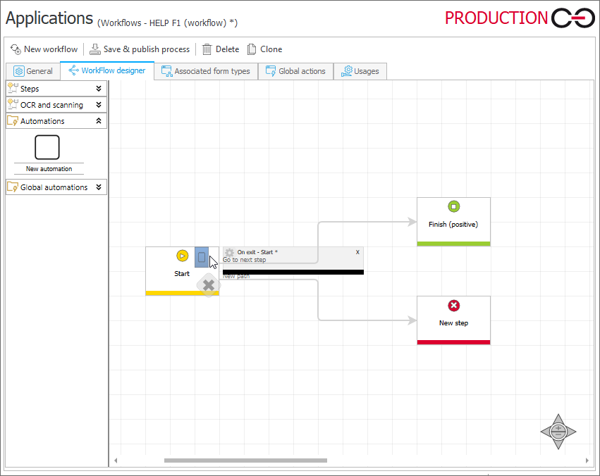
Once an automation is embedded, you can add an action to it. You can do that in a window that is opened automatically after dropping the automation in a selected location (the window can be also opened later on by double-clicking the gear icon). Additionally, a preview window opens after hovering mouse pointer over the gear icon. The window displays the actions configured in a given automation.
Designer tools
Once you open the WorkFlow designer tab, an additional Designer tab appears in the upper part of the Designer Studio window. The tab is placed inside a pink Designer tools ribbon. The tab includes a number of options described below.
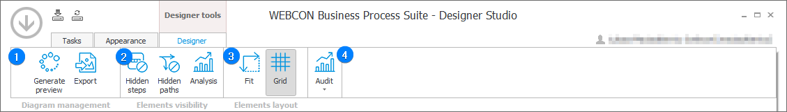
1. Diagram management
- Generate preview – adds a graphic diagram of the described workflow to the documentation.
- Export – a diagram area is exported into a graphic .png file.
2. Elements visibility
- Hidden steps – shows or hides steps that are defined as hidden in the process (marked with a dashed line).
- Hidden paths – shows or hides paths that are defined as hidden in the process (marked with a dashed line).
- Analysis – opens analysis view mode.
3. Elements layout
- Fit – zooms the diagram to fit it inside the window.
- Grid – displays a grid in the diagram area. When dragging or dropping steps, they are automatically aligned with the grid lines.
4. Audit
The functionality enables verification of the number of created instances in a specified time, counts the number of entries into a specified workflow step and the number of path transitions. The results are presented in a graphic form.
To learn more about the audit functionality, read the ARTICLE available on the WEBCON Community website.