Workflow designer
The tab allows you to create and visualize workflows in an easy and convenient manner.
Creating a workflow consists of the following operations:
- creating steps,
- adding paths to link steps,
- adding automations on a step or path.
To design a workflow, you can use a dedicated Designer tab displayed in the upper part of the Designer Studio window. Please note that it appears only after opening the Workflow designer tab in the workflow window.
Workflow designer window
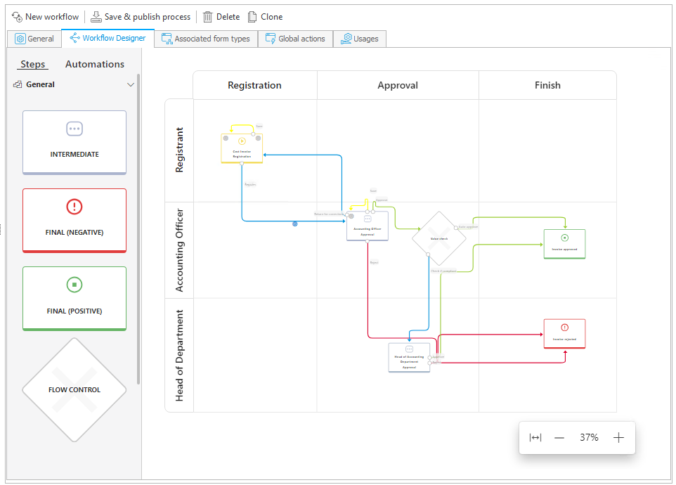
Steps/Automations
The panel on the left includes steps and automations which you can place on the diagram using the drag-and-drop method.
Please note that you can drop automations on path, on entry to a step or exit from it. Additional methods of invoking actions and automations are discussed in the Actions chapter.
You can use the Description field available in the step edition window to describe step function. This description is then displayed as a tooltip after hovering mouse pointer over the step icon in the diagram.
Working area
The central part of the Workflow designer is the area where the actual workflow is created. You can add notes here, which will also be visible in the Workflow designer in Portal.
Buttons for resizing the workflow preview
The buttons allow for zooming in and out of the Workflow designer. The Fit to screen button is used to automatically adjust the diagram size to the current window size. The zoom status and position in the preview are remembered and saved in the browser. In addition, it is possible to resize the diagram by holding the Ctrl key and scrolling.
Workflow components
Steps
A workflow step is a point where the workflow stops to enable execution of a task assigned to specified individuals. Such step is represented on the diagram in Designer Studio by a tile whose exact appearance depends on the type of a given step. You can add step tiles to the diagram with the drag-and-drop method. There are several step types available: Start, Intermediate, Final (positive), Final (negative), Wait for sub-workflows, System, and Workflow control.
Each workflow must contain a start step and at least one final step (positive or negative one). By default, when creating a new workflow (also within a new process), a start step and a positive end step are created and connected by a path.
By single-clicking a step tile, you select it, which is indicated by adding a frame to it. To open the step edition window, double-click the tile or right-click it and select the Edit step option from the context menu. In addition, you can click on the step name to change it directly.
Selecting the Show analysis option opens the Analysis window. More information is available IN THIS CHAPTER.
Paths
These elements logically connect steps and enable navigation between them (provided there is a bigger number of paths branching out from the step). On the diagram, paths are presented as lines connecting individual steps or returning to the same step. Each step can hold any number of outgoing and incoming paths. You can create paths on the diagram by clicking one of the white dots that appear after selecting a step, and dragging and dropping it on the target step.
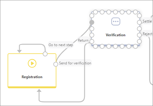
Path context menu
By right-clicking the path, you expand the context menu that includes a number of options.
- Edit path – opens path edition window,
- Show/Hide on diagram – allows you to hide / show a previously hidden path on the diagram. The hidden path is marked in gray,
- Remove path – deletes the selected path from the workflow, including automations embedded on it,
- Set path color – the node allows you to choose the path color. The path coloring function is especially useful in the case of complex workflows where it helps user to distinguish individual paths.
To learn more about configuring default values, read the ARTICLE available on the WEBCON Community website.
Workflow phases and actors
If the Enable workflow phases and Enable workflow actors options are checked on the General tab, dedicated areas will appear on the Workflow designer. The main purpose of these areas is to provide a visual representation of the steps and related tasks, divided according to the stages of execution (phases) and the people responsible for their completion (actors), respectively. Together, these features provide another layer of workflow visualization.
After enabling these functionalities, three default phases appear in the Workflow designer: Start, Execution, and Finish, as well as two actors: Actor 1 and Actor 2. By default, the entire workflow is placed in the Execution phase and/or at the Actor 1 level.
You can drag steps to any phase/actor field, as well as add and remove phases and actors using the menu available by clicking on their names. Selecting the Edit button (pencil icon) in this menu opens the Properties window, where it is possible to change the name, description and documentation of the phase/actor and their translations.
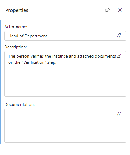
Directly on the diagram, it is also possible to change the size of individual phase/actor blocks, with a minimum size of 400 px.
For newly created applications, standard processes and their workflows, the Workflow phases functionality is automatically enabled – the start step is assigned to the Start phase and the end step to the Finish phase.
Information on defined phases and actors is also available in dedicated chapters of the documentation generated for a given process.
Automations
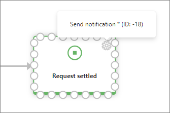
Apart from the above-mentioned steps and paths, the workflow designer allows you to embed automations, i.e. containers that include actions executed automatically by WEBCON BPS Workflow Service. They are available in the left panel of the WorkFlow designer window after expanding the Automations node. Similarly to the above-described steps and paths, automations are embedded by means of drag-and-drop method. You can put them in in three locations: on step entry or exit, or transition path (a gear icon informs about embedding an action). The location determines the sequence and the point at which an action is invoked while an instance progresses through the workflow.
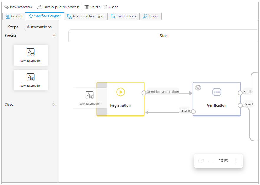
Once an automation is embedded, you can add an action to it. You can do that in a window that is opened automatically after dropping the automation in a selected location (the window can be also opened later on by double-clicking the gear icon). Additionally, If you hover your mouse over the cogwheel icon, the name of the configured automation is displayed.
Designer tools
Once you open the Workflow designer tab, an additional Designer tab appears in the upper part of the Designer Studio window. The tab is placed inside a pink Designer tools ribbon.
The tab contains two options in the Diagram management group:
- Save preview – after clicking on the button, the diagram preview is saved in the indicated location on the disk as an image file in .png format,
- Grid – displays a grid (in the form of dotted lines) in the diagram area. As you drag or drop steps, they automatically align with the grid lines.